Programming Voltage Ranges for Digital Inputs
Programming Voltage Ranges for Digital Inputs

The Digital Alarm Inputs on the Bridge are normally configured to enter and exit the alarm state in the presence of a simple short between the I and G terminals, but they can also be configured to expect custom voltage ranges. This option allows the bridge to be configured to work with the different alarm panel terminal options and resistance values. This article will demonstrate how to configure these values in portal.
 Ensure the input wiring has been accomplished as depicted in this Article
 A. Open the options on the camera channel that is associated with the input you plan to configure (Input 1 is the 'I' terminal on the far left hand side of the unit) by clicking the gear: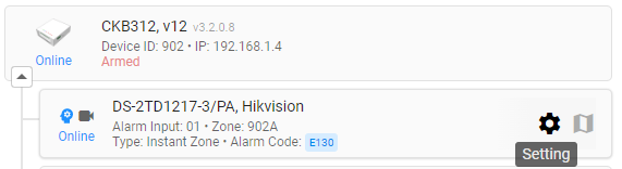
B. Select Alarm from the top tab options:
C. Click the "input voltage" line:
1. The "current status" is displayed here, which includes the current state of the input (open or closed) and alarm condition (Normal or Alarm).
- The color is red for "alarm," as depicted above, and blue for "normal" status:
2. The current "trigger type" (normally open or normally closed) and the current voltage detected on that input are depicted here.
3. Here users can edit the "trigger type" for that input.
4. Here users can select an alarm panel preset. This will edit the expected voltage on that input to account for the standard resistance on the selected alarm panel type.
- Use the drop down to select:
If you are using a sensor directly wired into the bridge without the alarm panel, choose the "Stand Alone No Panel" option.
5. This "edit voltage range" button will unlock the voltage selector nodes to adjust the sliders depicted and explained in 6. When activated, button will change to
6. The blue shaded areas depict the "open" and "closed" voltage ranges for that targeted input. The Orange line depicts the voltage that the bridge is currently detecting. Ideally, the orange bar is somewhere in the middle of the left hand shaded area in one state, and the right hand shaded bar in the other state. You can edit the ranges by moving the White nodes that appear when the button (5) is clicked:
Simply slide the nodes into the desired positions and hit the blue "save changes" button:
You should immediately see the update reflected in "current status" (1) after the save is applied.

This configuration step is also referenced during the initial hardware registration steps for new cameras. On step 6 (alarm programming), users will notice the same options in the "Alarm Trigger Source" area:
Click the "Customize DI Voltage" button to open the menu with the nodes and voltage slider. The same "voltage preset" options are accessible here as well:
Clicking "save changes" will apply the new voltage parameters and display the updated DI status immediately.
Related Articles
Alarm Panel Pairing: Programming with The Bridge
Alarm Panel Pairing Mode: When a Bridge is programming in Alarm Panel Pairing mode, the Bridge is a video alarm module to the on-site alarm system. The Bridge will capture video events for all alarm zone triggers. To change your Site Programming mode ...Programming Voltage Ranges for Bridge Arming Pin
Bridge hardware versions released after January 2019 have a voltage arming pin that allow the Bridge to follow the armed condition of an on-site alarm panel. Each alarm panel brand has a specific voltage output range that will follow the disarmed and ...Physical Triggers: Wiring Alarm Inputs on the Bridge
Depending on the device you are using to trigger the alarm zone on the bridge, there are a few ways you can wire into the bridge. Below are 3 examples of wiring the Bridge Alarm zones. 1. Zone Passthrough In this illustration, the Bridge is powered ...Adding Cameras to a CHeKT Bridge
Links to Additional Steps Creating A Site: Creating a New Customer Site Site Arming Method: Setting Site Arming Source Registering a Bridge: Registering a CHeKT Bridge Alarm Panel Wiring: Alarm Panel Pairing: Programming an Alarm Panel with The ...Alarm Panel Pairing: Configuring the Bridge Arming Options
Alarm Panel Pairing Mode When a Bridge is programming in Alarm Panel Pairing mode, the Bridge is a video alarm module to the on-site alarm system. The Bridge will capture video events for all alarm zone triggers. To change your Site Programming mode ...